Automatic Controllers for Power Factor Correction Banks
 The reactive power controller is an intrinsic part of PFC banks equipment which connects or disconnects capacitor stages automatically.
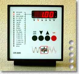
Power Factor Controller CONDENSOMATIC - CR 2000
The power factor controller CR 2000 calculates the actual and reactive power in the mains from the
measured current and voltage. It also determines if actual power is being consumed or delivered.
The controller identifies the power of the connected capacitor stages and connects or disconnects
them in an optimized manner as required by the actual mains conditions. The regulation considers the
frequency of changes in the reactive load and follows the principle of rotational switching.
This guarantees that optimum power factor correction is achieved with the minimum number of
switching operations. It is also possible to determine a fixed capacitor value which is always added
to the measured capacitor power. This is useful for the additional compensation of the reactive
power of a transformer.
The integrated digital display can show the actual power factor, the mains frequency, the actual
tariff, the programmed target power factor, the value of present harmonics, the connected and the
missing capacitor power. This makes general and specific monitoring of the capacitor bank and its
operating conditions possible.
The power factor controller CR 2000 is ready for operation with its preset functions immediately
after installation without any modifications or adjustments.
Indications of the display
- cos phi, U, I, S, P, Q, mains fre-quency
- 3rd...13th harmonic (V und I)
- memory for max values
- connected capacitor power
- missing capacitor power
- connected capacitor branches
- No of switching operations per branch to date
- notification about the reaching of a certain No of switching operations of a branch
- delivery of actual power (e.g. du-ring the operation of generators)
- alarm during insuffient or excessive voltage (±15% of the rated measu-ring voltage)
Further properties
- 4-quadrant-operation
- automatical identification of the power of connected capacitors
- optimized switching
- automatic and manual operation
- port for connection of a tariff switch
- separate setting of target and alarm cos
 for two different tariffs
- port for external alarm
- adjustment of the switching periods in dependence of the load
- alarm during insufficient measuring current
- disconnection of the capacitor bank in the event of excessive har-monic voltage distortion
- detection and disconnection of defective capacitor branches (i.e. permanent decrease of 20% below the initial value)
- variable time for alarm in the event of failed power factor correction (30 - 300 min)
- zero voltage disconnection
- definition of a permanent capacitor value in addition to the measu-red required power, e.g. for compensation of a transformer
- optional RS485 port for PC or remote control unit
 General Technical Data
Power Factor Measuring Devices
UM 2000 - The universal measuring device
The UM 200 is based on an electronic single phase measuring system and can be used in three phase networks with symmetrical or nearly symmetrical loads.
The device works in all four quadrants and can be connected without regard to phase, phase angle or current direction. The measuring range covers voltages
from 58 to 690V at 50 and 60 Hz, the measuring current range is designed for current transformers of the usual types i.e. .../5 or .../1A.

PF 2000 - The electronic power factor meter
The PF 2000 takes this trend into consideration and - by means of a special measuring method - determines the power factor independently from the actual shape of the sinewave.
The 4-quadrant measuring principle ensures that the power factor is determined correctly whether the power is being imported or exportes.
The device operates on a sinlge phase measuring system, i.e. in three-phase mains it shows the cos of the phase in which the current transformer is installed.
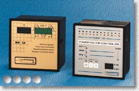
Other Automatic Controllers for Power Factor Correction Banks
The electronic measuring system operates according to the principle of current-time-integral. The measurement is made independently of the
current waveform, permitting the application of the controllers in networks with thyristor controlled equipment.
The controller continuously monitors the reactive and real vectors of the current in the current and voltage path. By using this data the relay
computes the actual power factor which is compared with the target power factor. Any differential results in the capacitor contactors being
switched on or off.
Threshold values can be determined by hand or - in the case of BLR-CA automatically according to capacitive stage power, line voltage and
current transformer ratio. When a stage ratio of 1:1:1 ... is used, the rotation switching leads to an equal distribution of switching
frequencies for all contactors and capacitors, allowing for longer period for discharge of the capacitors. In the case of oter ratios (e.g. 1:2:2:2
or 1:2:4:4) all equal stages are switched by the rotation method.
In the interest of the equipments preservation, the stage which is supposed to meet the compensation requirement most effectively will be
selected. Any unnecessary activation is thus avoided.
General Technical Data
Home